

-
Products
Overview Products

-
2D Cutting
-
Tube Cutting
-
3D Cutting
-
Intelligent Welding
-
Intelligent Cutting Head
-
Industrial Automation
-
Industrial Software
-
Combination
-
Combination
BOCHU New Product -
Combination
BOCHU New Product -
Controller
BOCHU New Product -
2D Cutting Head
Tube Cutting Head
3D Cutting Head
Consumables
BOCHU New Product -
Servo
BOCHU New Product -
Industrial 4.0
-
- Support
- About
- Online Store


- Software Download
- Manual
- Video
- Tutorial
I. Introduction
Start Point is the initial point of a toolpath. The Start Point function can be used to modify the start point of a toolpath. With the Batch Modify Start Point function, you can quickly adjust the start points of multiple part toolpaths to more suitable cutting positions.
II. How to Use
1. Manual Modify Start Point
Click Start Point in the Technique Setup bar, and then click the toolpath where you want to change the start point.

2. Batch Modify Start Point
Click Batch Modify Start Point in the drop-down menu of the Start Point in the Technique Setup bar.

① Application Range

Parameter definitions:
Selected graphics on the current screen: Apply batch modification to the currently selected toolpaths.
All graphics on the current screen: Apply batch modification to all displayed parts in the current interface.
All nestings: Apply batch modification to all toolpaths in all nesting results.
② How to Modify Start Point on Cutoff Line/Tube Holes

To set the start point on cutoff line or tube holes, select the corresponding checkboxes; otherwise, the options are disabled (grayed out).
Click the green arrow beside By sorting priority to adjust the order. When multiple conditions for batch modification are met, the system determines the start point according to the set priority, from top to bottom.
It is recommended to enable Avoid vertex and Avoid corner. Since vertices and corners are not ideal for piercing, starting from those positions may cause unstable following.
Parameter definitions are as follows:
| Parameter | Description | Illustration |
| Angle with X axis | The angle between the start point and the X-axis from the cross-sectional view of the part. Range: 0° to 180°. |  |
| Far end | The maximum Y-axis coordinate of the current toolpath. |  |
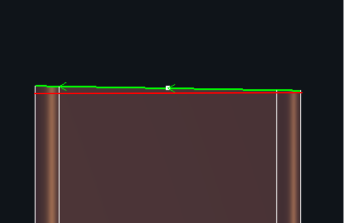
| Near end | The minimum Y-axis coordinate of the current toolpath. | |
| Long edge midpsoint | The midpsoint of the longest edge. |
|
| Vertex | The corner positions of the tube hole. |  |
| Max Z | The maximum Z-axis coordinate of the current toolpath. |


③ Accuracy Settings

Same precision: In actual modeling, some toolpaths may appear aligned in the Y-axis but actually differ by a small distance, sometimes even a few millimeters. The same precision value defines the tolerance within which these deviations are ignored, treating the Y-coordinates as the same.
E.g., if the start point is set to Far end + Long edge midpsoint, without Same precision, the start point may fall on the Far end (such as a chamfer). With Same precision applied, deviations within the tolerance are ignored, and the start point can be placed at the Long edge midpsoint instead.
IIII. FAQs
1. After modifying the start point, why is it not applied after clicking OK?
① Check if the Apply to setting in the Batch Modify Start Point is set correctly.
② Start point modification does not apply to special toolpaths on angle sections, channel sections, or I-beam profiles!
I. Introduction
Start Point is the initial point of a toolpath. The Start Point function can be used to modify the start point of a toolpath. With the Batch Modify Start Point function, you can quickly adjust the start points of multiple part toolpaths to more suitable cutting positions.
II. How to Use
1. Manual Modify Start Point
Click Start Point in the Technique Setup bar, and then click the toolpath where you want to change the start point.
2. Batch Modify Start Point
Click Batch Modify Start Point in the drop-down menu of the Start Point in the Technique Setup bar.
① Application Range
Parameter definitions:
Selected graphics on the current screen: Apply batch modification to the currently selected toolpaths.
All graphics on the current screen: Apply batch modification to all displayed parts in the current interface.
All nestings: Apply batch modification to all toolpaths in all nesting results.
② How to Modify Start Point on Cutoff Line/Tube Holes
To set the start point on cutoff line or tube holes, select the corresponding checkboxes; otherwise, the options are disabled (grayed out).
Click the green arrow beside By sorting priority to adjust the order. When multiple conditions for batch modification are met, the system determines the start point according to the set priority, from top to bottom.
It is recommended to enable Avoid vertex and Avoid corner. Since vertices and corners are not ideal for piercing, starting from those positions may cause unstable following.
Parameter definitions are as follows:
| Parameter | Description | Illustration |
| Angle with X axis | The angle between the start point and the X-axis from the cross-sectional view of the part. Range: 0° to 180°. | |
| Far end | The maximum Y-axis coordinate of the current toolpath. | |
| Near end | The minimum Y-axis coordinate of the current toolpath. | |
| Long edge midpsoint | The midpsoint of the longest edge. |
|
| Vertex | The corner positions of the tube hole. | |
| Max Z | The maximum Z-axis coordinate of the current toolpath. |
③ Accuracy Settings
Same precision: In actual modeling, some toolpaths may appear aligned in the Y-axis but actually differ by a small distance, sometimes even a few millimeters. The same precision value defines the tolerance within which these deviations are ignored, treating the Y-coordinates as the same.
E.g., if the start point is set to Far end + Long edge midpsoint, without Same precision, the start point may fall on the Far end (such as a chamfer). With Same precision applied, deviations within the tolerance are ignored, and the start point can be placed at the Long edge midpsoint instead.
IIII. FAQs
1. After modifying the start point, why is it not applied after clicking OK?
① Check if the Apply to setting in the Batch Modify Start Point is set correctly.
② Start point modification does not apply to special toolpaths on angle sections, channel sections, or I-beam profiles!

